- Interfacing the LIDAR
- Motor Connector
- Data and Power Connector
- Motor Port Mode
- Sensor Port Mode
- LIDAR Rotational Geometry
- Testing the LIDAR
- Libraries
- Mechanical Integration
- Laser Specs and Safety
- Get Help
- References
Interfacing the LIDAR
XV11 LIDAR communicates using UART, 8N1 at 3.3V with baud rate 115200.
EV3 has all the required hardware to communicate with the LIDAR and ev3dev has the software.
The instructions on this page apply to EV3. You can also get it working with Raspberry PI and BrickPI but BrickPI doesn’t support other-uart mode for sensor port and dedicated Raspberry Pi UART GPIO pins are already taken by BrickPI. You have to figure out some other way to get the UART. USB to UART bridge could be one option.
To interface the LIDAR one has to:
- Solder the connector for LIDAR motor
- Solder the connector for LIDAR data and power
- Put the EV3 output port in dc-motor mode
- Put the EV3 input port in other-uart mode
- Spin the LIDAR motor CCW with speed around 300 RPM
- Read LIDAR data using UART
For the details, follow video tutorial:
Use the simplified 2-wire way of soldering the motor connector. No resistors needed. See below.
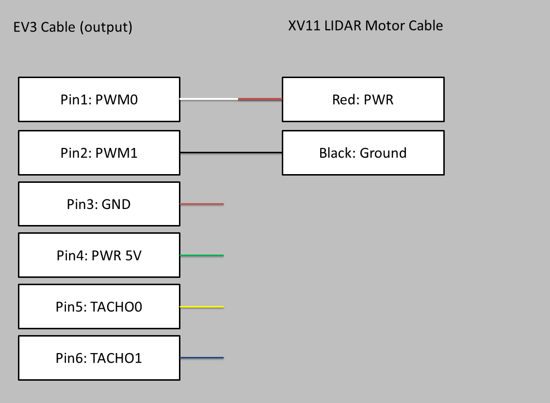
Motor Connector
You will need half of EV3 cable, header mating JST PH 2.0mm pitch connector with 2 pins and heat shrink tubes.
 LIDAR motor connector scheme
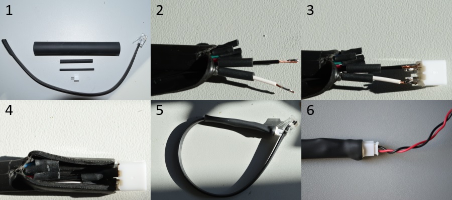 1 - materials 2 - strip wire 3 - solder connector 4 - heat shrink tubing 5 - the connector 6 - connected
With the above scheme use positive duty cycle to drive the motor counterclockwise.
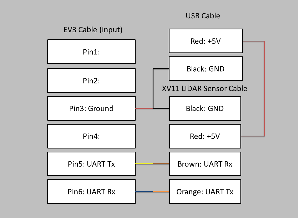
Data and Power Connector
You will need half of EV3 cable, half of USB cable, header mating JST PH 2.0mm pitch connector with 4 pins and heat shrink tubes.
 LIDAR data connector scheme
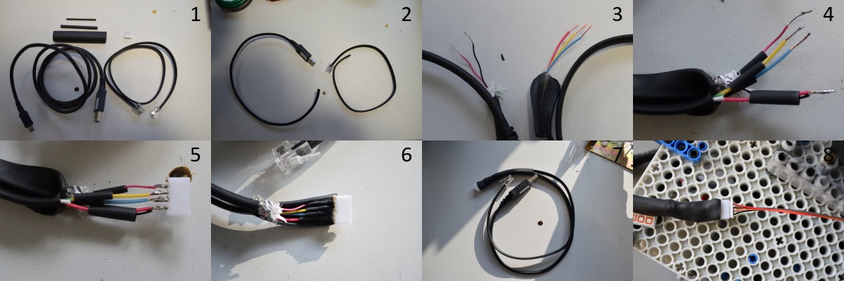 1 - materials 2 - cut the cables 3 - strip wire 4 - solder grounds 5 - solder connector 6 - heat shrink tubing 7 - the connector 8 - connected
The USB power connector is also reference potential for the UART lines. Plug USB power connector to EV3 or passive (non-powered) USB hub connected to EV3. LIDAR consumes around 135 mA from USB. EV3 has enough power to supply 2 LIDARS and reasonable Wi-Fi dongle.
Motor Port Mode
LIDAR should be spinning counterclockwise at around 200-300 RPM. With the wiring from this tutorial use positive duty cycle around 45 to spin counterclockwise at around 300 RPM.
I am assuming your motor connector is connected to port A and it is the only motor.
First, you have to put the motor port in dc-motor mode:
echo dc-motor > /sys/class/lego-port/port4/mode
Then your motor interface will be available at:
/sys/class/dc-motor/motor0
Sensor Port Mode
Plug USB power connector to EV3 or passive (non-powered) USB hub connected to EV3, not to other device. The USB power connector is also reference potential for the UART lines.
I am assuming your data connector is connected to port 1 (adjust commands otherwise).
You will have to put the sensor port in other-uart mode:
echo other-uart > /sys/class/lego-port/port0/mode
You can read and write to or from LIDAR at:
/dev/tty_in1
It is binary tty communication. More information in Testing the LIDAR section.
LIDAR Rotational Geometry
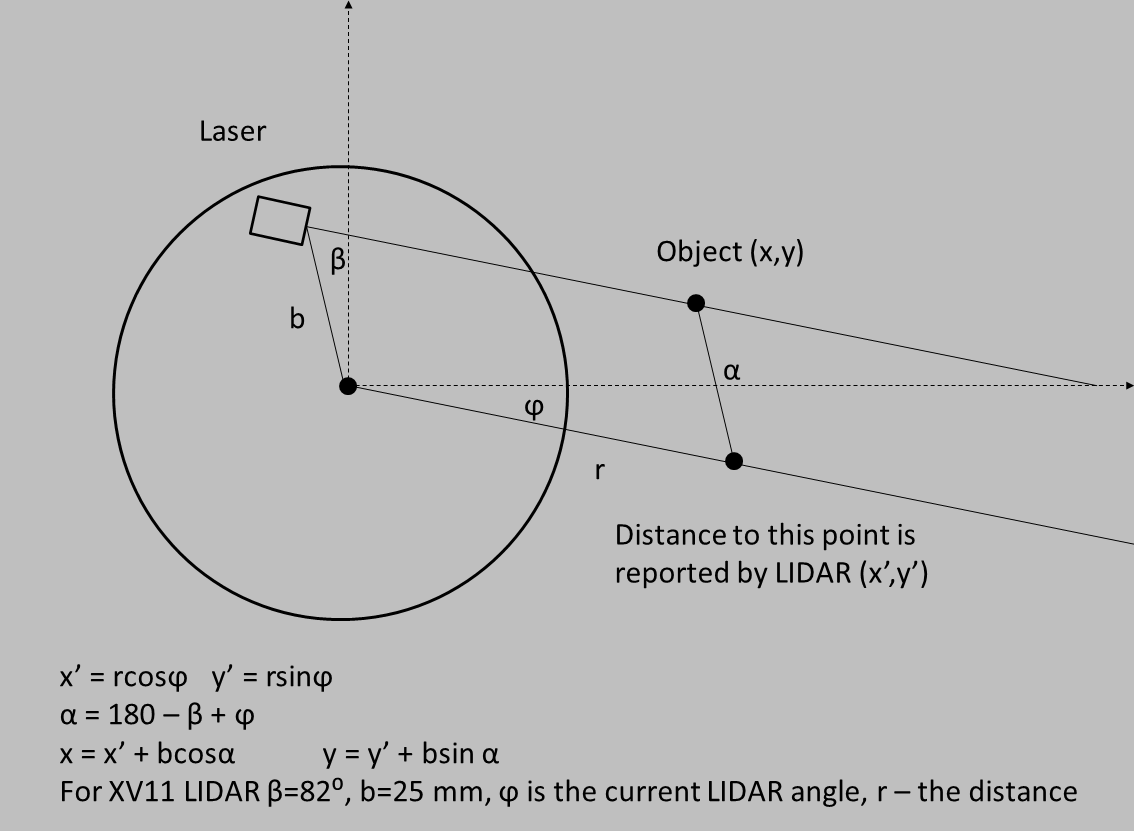
If you assume that XV11 LIDAR returns you the distance to the object you will have it almost right. To do it correctly take into account the rotational geometry of the LIDAR.
The scheme below is for Revo LDS. For XV11 it is enough to change some signs. See xv11lidar-test for detailed formulas.
 Revo LDS rotational geometry
You may ignore the above and the reported distance will still be approximately correct. You will introduce systematic error, dependent on angle, bounded by 25 mm on x and y. Regardless, the LIDAR has also random error with variance dependent on distance, surface and reflection angle.
Testing the LIDAR
If your EV3 connects using Wi-Fi adapter you need passive (non-powered) USB hub to power the laser and Wi-Fi. LIDAR power has to be drawn from EV3 (or USB hub connected to EV3) in order to have the right UART reference potential.
Interested to see LIDAR output in realtime? Follow ev3dev-mapping
Interested in LIDAR geometry and internals? Follow xv11test
xv11test
You can use xv11test from the github repository to:
- test the LIDAR
- plot the LIDAR scan
- get idea how to interpret the LIDAR output and apply geometric correction
Follow readme.md in xv11lidar-test repository.
ev3dev-mapping
Plot the readings in real-time with ev3dev-mapping
Get Unity on your PC. While it’s installing:
- on EV3 follow Building Instructions at ev3dev-mapping-modules
- on PC follow Installation Instructions at ev3dev-mapping-ui
On EV3 plug LIDAR data connector to port 1, LIDAR power connector to USB, motor connector to port C and:
cd ev3dev-mapping-modules/bin
./TestingTheLIDAR.sh # put in/out ports to other-uart/dc-motor modes
./ev3control 8004 500 # start ev3control with UDP port and timeout
On PC open ev3dev-mapping-ui in Unity and follow the steps below:
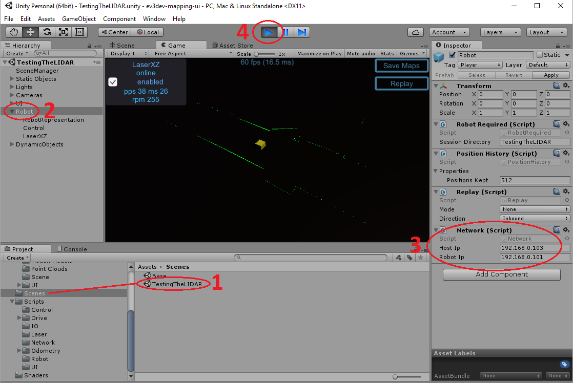 ev3dev-mapping-ui - 1 - open the scene 2 - select Robot object 3 - set IP addresses 4 - hit play
Libraries
xv11lidar is a simple low-level C library with just 3 functions - InitLaser, ReadLaser and CloseLaser.
Library takes care of LIDAR communication and you can handle the motor with one of ev3dev libraries or shell script.
Mechanical Integration
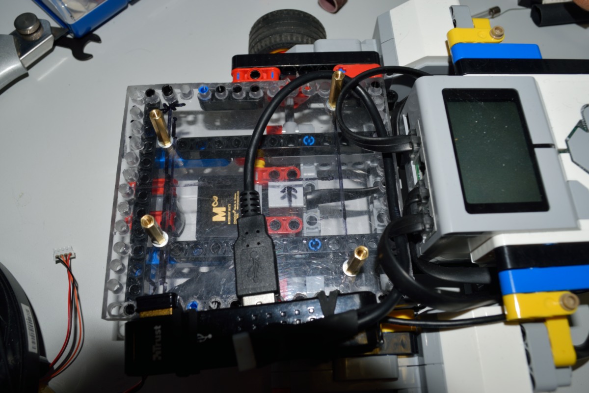
At some point you will want to install the LIDAR on the robot. You can make inexpensive stand compatible with LEGO from polycarbonate, acrylic plastic or even wood. I choose polycarbonate. Make a plate 120 mm x 104 mm (this corresponds to 15 and 13 thick technic beams). I did it a bit too thick - 8 mm but if you connect it to your construction from only one side this doesn’t matter. Order same spacers (25 mm high for M3 screws are ok). Drill the holes for spacers and technic pins. My XV11 LIDAR plate below was meant as first experiment but ended right in the robot. A lot of technic pin holes are out of place but there were just enough made right to fix the plate to the robot.
Everything for just a few € or $.
 LIDAR stand from polycarbonate with M3 screws spacers
Laser Specs and Safety
You can find laser technical parameters on Neato website - see laser specs, the Compliance information section.
According to this documentation the laser is class 1 device. It means that it is safe under all conditions of normal use.
Whether our use is normal is disputable. See wikipedia entry on laser safety class 1 if you are concerned.
Despite some contrary information on the internet the XV11 laser is in the visible range of light. It is possible to see the laser dot if looking at exactly correct angle. The laser pulse duration is only 200 microseconds so you would see a blinking dot on every revolution.
Quite obviously I am not encouraging you to do that and if you do, you’re doing it at own risk.
Get Help
We keep track of problems related to LIDAR interfacing on xv11lidar-test issues tracker. Please don’t email the developers directly unless you have a personal question.
Note: The ev3dev-mapping and xv11lidar repositories have their own ev3dev-mapping issues and xv11lidar issues trackers.
If you don’t find anything helpful by searching, then create a new issue (only one problem, question or suggestion per issue please).
References
xv11hacking - for even more information on LIDAR integration
Revo LDS Whitepaper - for an article describing Revo LDS, written by the engineers from Neato Robotics. XV11 LIDAR is not exactly Revo LDS but they share a lot of design
laser specs - for laser specification from official Neato site
laser safety class 1 - for wikipedia entry on laser safety classes
JST PH 2.0mm pitch - the LIDAR connector, 4 pins for data, 2 pins for motor
xv11lidar-test - repository for testing and learning how to work with the LIDAR
ev3dev-mapping - meta-repository grouping ev3dev-mapping subprojects
ev3dev-mapping-modules - EV3 side modules of ev3dev-mapping
ev3dev-mapping-ui - PC side visualization/control of ev3dev-mapping
Unity - the Unity engine
